ATV Channel Separation Requirement
A normal broadcast TV channel is 6 MHz wide. In any given area, the adjacent channel is skipped because the TV sets IF filter cannot reject an over the air stronger signal on that adjacent channel without interfering with the weaker on channel signal. Signals that are down to 40 - 50 dB less than the desired video carrier and are within the 6 MHz pass band can be seen in the video. On cable they rigorously equalize the amplitudes and filter each 6 MHz channel so that every channel can be used.
The strong vs weak signal rejection is the reason why there is only room for 2 ATV channels in the 70 cm band. Ideally the video carriers need to be separated by at least 10 MHz so that the usual ATV DSB transmitters lower sound and color subcarriers do not fall within the passband of the upper VSB of the other channel.
So that means anyone transmitting on 439.25 could interfere with someone receiving on 434.0 depending on the relative signal strength of the 439.25 lower sound and color subcarriers to the 434 video carrier. Amateur VSB filters in the antenna line can reduce the transmitted LSB sound subcarrier another 15 dB but most will not pay the $300 to $400 for home use, and it could only be use for simplex unless you could place it before the T/R relay.
In areas that cannot use 439.25 because of other mode users, 434 repeater input can be used and still pair with 421.25 output with enough separation. 421.25 is not very practical for simplex use because of the VSB filter requirement, so 426.25 or 427.25 can be used for simplex depending on the locations, beam headings, distance and power. 434 LSB sound is within the passband of 426.25 or 427.25 so that is why 434 is used for repeater input rather than vice-versa since the repeater receiver is usually on a high hill top and has a higher probability of seeing more 426.25 or 427.25 MHz transmitters than if it is used for simplex.
434 does not see the USB of a 426.25 or 427.25 MHz signal because the TV receiver filter rolls off at the channel edge 1.25 MHz below the video carrier frequency. The top edge is 4.75 MHz above the video carrier.
A FM voice transmitter below 444.0 will be within the 439.25 ATV receivers passband and interfere depending on the relative signal strengths. FM voice stations may have more possibility of interference than ATV because the sound subcarrier is no stronger than 15 dB down from the video carrier.
As far as signal strength it is all relative when it comes to interference.
ATV Channel Spacing
Most areas have their ATV frequencies as part of a local band plan. But as the band is used more by all modes, there are technical considerations that need to be addressed if the local band plan is revised or an all new one configured.
Ideal AM ATV channel spacing would be same as broadcast - 12 MHz (10 MHz exception in the case of channel 4 and 5). This is what was done with the 1200 MHz band plan (5 channels starting at 1241.25 in 6 MHz band width channels) which was the first time a band plan was done from an engineering standpoint rather than a consensus of what was being used by a few at the time. On the 400 and 900 MHz band there is only room for 2 ATV channels in any given area.
On 900 MHz the spacing is 12 or 13MHz originally depending on where you are, but the Automatic Vehicle monitoring system people made us move from 910.25 simplex and 923.25 repeater output, to avoid their transmissions and this will vary from area to area and just have to take the interference since they are primary.
On the 400 MHz band, if the local ATV community elects to have an inband repeater, at least 12 MHz is necessary in order for the VSB filters to do their job of rejection to prevent desense and thus take the only 2 channels available. Because of the sound subcarrier being +/- 4.5 MHz on each side of the video carrier, only 2 channels are available for ATV in any given area without overlap and interference. For this reason, 439.25 or 434.0 are chosen for the high end of the band, and 427.25, 426.25 or 421.25 MHz for the low end of the band. 421.25 is only used for repeater output because the lower sideband 4.5 MHz sound would be outside the 420 MHz band edge as well as any video carrier frequency below 425 MHz and requires a VSB filter in the antenna line to attenuate the out of band energy. The DCI 8 pole VSB filter has the best attenuation slope from those I have tested (International Crystal, Spectrum International and TX-RX Systems being the others). Ideally 434.0 or 439.25 can be inputs with 421.25 output. 439.25 and 426.25 can be respective input and output, or vice-versa, but 434.0 can only be an input with 421.25 output to get enough separation. Some areas have switched to 426.25 in and 439.25 output to minimize interference from FM voice repeaters below 444.0. Technically 427.25 cannot be used for a repeater because the sound subcarrier falls within the 431-433 weak signal restriction - however it is used in some areas due to military radar interference and no real problem to 432.0 weak signal operation.
The common ATV video carrier frequencies are taken from various local band plans and most predate the popularity of cable television. Only by coincidence are 421.25, 427.25 and 439.25 the same as cable channels 57, 58 and 60 respectively. 426.25 and 434.0 are well within the AFC locking range of cable tuners in TV sets to receive on cable channels 58 and 59. AFC in most TV's will lock +/- 1 to 2 MHz from center channel frequency.
434.0 was selected instead of the standard cable TV channel 59 of 433.25 out of consideration to the weak signal members on our technical committee who wanted more separation eventhough the video sidebands are down 35 or more dB +/- 1 MHz from the video carrier. It also puts the sound subcarrier (15 dB down) above the satellite segment of 435-438 (438.5 MHz). The color subcarrier is more than 22 dB down worse case (all red picture), typically 35 dB or more, eventhough in the satellite segment (437.58) and has not caused any interference here in the over 20 years it has been used. There are no satellites on this frequency presently. Legally, the repeater owner would only have to attenuate the color frequency 4 more dB with a notch filter to fall under the -26 dB FCC mean power definition of bandwidth, but it has never come up anywhere that I know of.
If the local ATV community elects to go crossband repeat, the least cost to the user and most efficient distance wise is to have the input on the 400 MHz band and the output on 900 or 1200 MHz (900 MHz goes half the distance that 400 MHz does given the same power and antenna gains plus it is easier to remove the higher coax loss of the higher bands with a preamp at the antenna rather than a transmit power amp). If one 400 MHz band TV channel is used for cross band repeater input, the other can be used for simplex and may not need the full 12 MHz separation depending on relative signal strengths. We use 434.0 repeater input and 426.25 simplex here in Southern California with only rare occasional interference. Our bandplans can be seen at www.scrrba.org.
ATV Emission Bandwidth
We hear all kinds of numbers thrown around for ATV bandwidth. Those looking for spectrum for other modes most often have a false impression if not defined correctly to them. No wonder they think we are band hogs. Most I have talked to think in terms of FM where the spectrum power density is quite high over the whole bandwidth - not so with AM ATV. Bandwidth really depends on what one is talking about, so here are some definitions.
Occupied Bandwidth: Per FCC Rules 97.3(a)(8) it is the width of a frequency band outside of which the mean power of the transmitted signal is at least 26 dB below the mean power of the transmitted signal within the band.
ATV Transmitted Bandwidth: Down greater than 40 dBc +/- 1 MHz of the video carrier (Television Engineering Handbook - 1992 - Benson - Fig. 5-11) plus color subcarrier at 3.58 MHz Down greater than 22 dBc (all red screen worst case but typically in a camera video picture below the -26dB mean power) and sound subcarrier 4.5 MHz greater than 15 dBc. Note this is true for both DSB and VSB. VSB has lower color and sound subcarriers attenuated additionally by the VSB filter response curve starting at -1.25 MHz below the video carrier.
Standard TV channel bandwidth: 6 MHz, video carrier 1.25 MHz up from lower edge.
While the transmitted video is many tens of dB below the peak envelope power (sync tip) and random (not unlike spread spectrum) the TV receiver IF and detector bandwidth must be almost flat across the whole 4.2 MHz to maintain the transmitted relative video to sync ratio. Normal instantaneous luminance video response bandwidth: 3 MHz.
Highest instantaneous video response bandwidth including color: 4.2 MHz
This is why most ATV stations receive more interference than transmit it. Most narrow band modes will never notice an ATV transmitter on the air if they are operating between 1 and 3.4 MHz or 3.8 and 4.3 MHz from a video carrier. The actual spectrum power density is about the same as license free 902-928 MHz FCC part 15 field strength with a 10 Watt 70cm AM ATV transmitter in these 2.4 and .5 MHz segments within the ATV channel. However, any narrow band transmissions greater than one microvolt within the 6 MHz channel can interfere with the picture.
ATV Receive Sensitivity
If you had a perfect AM ATV receiver with zero noise figure, the noise power floor with 3 MHz bandwidth is .8 uV or -109 dBm at standard temperature. The 3 db down detection bandwidth in the typical TV set is 3 MHz. The preamp stage in our downconverters are about 1 dB noise figure as well as most good external preamps. So the practical floor where you can see sync bars is about 1 microvolt at the input to the first stage - I added a dB for the rest of the system. Therefore you need about 200 microvolts for snow free pictures with an AM ATV system - 46 dB signal to noise which is about all one can get with home camcorder video. FM sensitivity is also dependent on the bandwidth and since FM ATV is much wider, the noise floor is higher. Noise floor for a 17 MHz wide FM ATV receiver used for 4 MHz deviation and 5.5 MHz sound is about 3 uV.
Coax loss reduces the sensitivity if looking from the antenna as the start of your system. So putting a 1 dB noise figure (NF) preamp at the antenna will eliminate what ever the coax loss is and bring the receiver system back to noise floor limit. Most TV sets do not need more than 15 dB gain ahead of them to get to the noise floor limit, so preamp or downconverter gain is not nearly as great a factor as the first stage noise figure. In fact more gain just pumps up the IF AGC and limits your dynamic range and makes you more susceptable to intermods. Most preamps are very wide band and amplify a lot of strong out of band signals into the system which can interfere with the desired weak signal ATV.
Bottom line is choose an antenna mounted preamp with 1 dB noise figure and no more than 10 dB + coax loss in dB gain for the best system sensitivity given the same antenna. There are preamps that have automatic T/R switching if you want to also transmit throught the same antenna. The only way to improve past this, assuming line of sight, is a higher gain antenna.
ATV vs. other modes on the 70cm band
In a band planning or discussion with FM voice people who seem to want to remove ATV from 70cm thinking that it takes up too much bandwidth, could interfere or FM will need the room to expand, here is some info and facts to fire back:
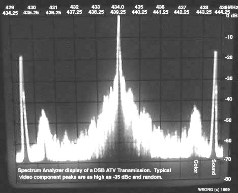
434.0 ATV repeater input does not conflict with the prohibition of repeaters using 431.0 to 433.0 or 435.0 to 438.0 MHz because the spectrum power density of the transmitted video sidebands is below the FCC -26 dB mean power definition of occupied bandwidth within these segments - see the attached spectrum analyzer photo. Also 434.0 ATV does not conflit with the intent of the FCC Rule 97.205(b). The energy in the video sidebands is so low and random that ATV does not interfere with weak signal or satellite modes of operation. Also ATV repeaters are designed to only key up upon sensing horizontal sync - other modes in the prohibited segments will not key an ATV repeater using the 434.0 MHz video carrier frequency.
Just how many FM voice channels are needed in any given communications area? ATV needs just two and if properly selected can result in more than enough FM voice channels. At first look it would seem that the limit would be that 40 channels from 444 to 445 is all that could be used since 439.25 ATV goes up to 444.0 MHz.
From the photo and referencing 439.25, there are actually 128 FM voice channels at 25 kHz spacing between 441 and 445 MHz available depending on terrain separation, cross polarization and other variables that will allow operating FM voice repeaters within the low energy sections of the ATV video sideband, especially if the FM Repeater uses high in and low out. I noted few video sideband pulses on the screen that did not take on the photo that never got above -35 dBc of the video carrier. Add in 20 dB of opposite polarity antenna loss and that gives 55 dB down of random video sideband power that could possibly get into an FM voice Receiver. Actually it is a little better than 55 dB given the receiver audio response curve roll off, more like 60 dB per a test I made where I connected my Kenwood TS790A multiband transceiver to a dsb video signal generator on 434.0 and tuned through 435 to 438 MHz looking for video noise.
Example: an ATV repeater transmitting 150 watts pep out of its amp (+52 dBm), 3 dB VSB filter and coax loss (+49 dBm), 5 dB gain from a horizontal omni gives an ERP of +54 dBm. The sideband energy is random at any given FM channel but would be at an ERP of -1 dBm or the equivalent of a little less than 1 milliwatt given the -55 dBc to FM voice cross polarized receivers - not much power to get very far, and you can play with the dBm's to fit your case. However for this to work, the ATV repeater cannot be located near a FM repeater site for both desense and creation of final amp generated intermod since they share the same bandpass and would not be able to reject the others inband signal. In addition, the color and sound subcarrier frequencies must not be coordinated for FM voice +/- 200 KHz each side at 442.83 and 443.75 MHz. But again, this leaves 128 possible channels in the area. I suggest that tests be made in any given area with FM voice repeaters to verify the co-channel compatibility between the ATV repeater and FM voice sites to prove to both sides.
There is little possibility of FM Mobiles hearing any video interference assuming line of sight and 5 or miles away. FM voice also has a good capture ratio and CTCSS to reduce unwanted signals from interfering. However, ATVers will see interference in the video from a FM voice repeater transmitting with in its pass band and line of sight. But ATVers usually use a beam to receive the repeater which will probably have the FM voice repeater in the null off the side of the beam. One microvolt is the common maximum acceptable interfering signal input to an ATV receiver when figuring out co-channel possibilities. This is the normal noise floor of an ATV receiver and where one can just barely see the cross hatch from a CW signal in a just snow free video signal between 100 and 200 microvolts.
Normal camera video does not have large sharp white to black rise times in the picture that produce significant side band energy above 1 MHz from the carrier. Most people have the impression that the video sidebands are like a sine wave or CW carrier. They are not, but are more like pulses that occur at the horizontal and vertical sweep rate depending on their contrast and vertical percentage in the picture. The pulse rise time is usually too fast for the FM audio receivers to respond to it. But there are video patterns that should be avoided or at least verified before putting on an ATV repeater if co-channeling with other modes close by. An all red picture can boost the color subcarrier up to -22 dBc. A multiburst test pattern that goes the full vertical length in the picture can boost sidebands to -18 dBc. Computer generated ID's can also give pulse sidebands greater than -35 dBc.
If 434.0 is used instead of 439.25 the number of FM repeater channels can go from 128 to as many as 200 and no special terrain separation necessary. With 434 ATV, 438.7 up can be used for digital, links, simplex autopatch, crossband repeaters or what ever combination an area sees fit with out conflict.
For the same reason given, with the 150 watt ATV repeater example 434.0 ATV (or thelower sideband of 439.25 MHz) does not interfere with 432 weak signal or 435-438 satellite because the spectrum power density is down more than 35 dB with a normal 100 % camera video modulated ATV picture in these segments. Here, vertical polarization is used in order to be crossed polarized to 432 weak signal operators. See figure 12.61 in the 1995-2002 ARRL Handbook or checkout any broadcast TV station or ATV station on a spectrum analyzer yourself. On the air verification with satellite users in So. California from the Jet Propolsion Lab Radio Club.
At the low end of the 70cm band, 420-431MHz, ATVers have to select 421.25 if they want an inband repeater or 426.25 if they want crossband or simplex, but not both in any one communications area. That gives at least 100 channels for FM links based on 25 kHz spacing. Duplex links can use 3 MHz spacing - a commercial standard at 420.
Packet can use 431.0-431.6 in channel spacings dependent on bandwidth vs baud rate. Since packet is not a repeater in the FCC definition, and weak signal ops have determined that they only need a 300 kHz buffer, packet is legal in this segment.
Therefore, there is no good technical reason FM voice people should tell ATVers they should not be on the 70cm band when there is plenty of room for all. Since there is plenty of room for all on a sound technical band plan basis, any frequency coordinator, group or person that prevents a licensed amateur from using the mode they choose could be liable for denying a civil right. Like wise ATVers need to consider their actual spectrum requirements and make all attempts to work out spectrum sharing with all other mode users based on sound engineering judgement.
Video RF Interference
Some camcorders and cameras are more RF susecptable than others and do strange things when connected to an ATV transmitter or near the antenna - the color goes crazy, auto iris shuts down or sync buzz in the audio.
Radiation from an antenna getting into a poorly (if at all) shielded camera can be reduced by moving either or both, or shielding the camera with foil. Keep the camera out of the main radiation lobes of the antenna as much as practical. It's easy to do at the home station where the antenna is on the tower or roof, but portable, mobile or R/C is where the problem usually shows up. Try to get the antenna as high as practical for both RFI and DX reasons and the camera placed at the null of the antenna pattern.
Conducted RF interference through the video and audio lines from the transmitter can be reduced by putting a 33 to 100 pF cap with very short leads right at the video and audio chassis connectors and in the more severe cases, a .22 uH RFC in series with the connecting wire to the respective connector. Ferrite beads are not used because they have no permeability left and no affect on frequencies above 200 MHz.
The low value disc cap and .22 uH is some times necessary in repeater receivers and transmitters to solve tough desense problems when all shielding, band pass filtering and antenna separation dont clear it up completely. The video lines usually have a low pass filter and bypass caps on the connectors, but often the audio lines do not and are the source of conducted RF from the transmitter into the repeater receiver.
Go to: