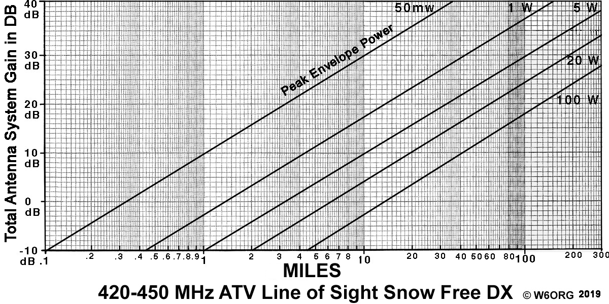
To find the distance, find the transmit and receive antenna systems Total gain dB horizontal line and go across to your your transmitters peak envelope power diagonal line and then go down from that intersection point to find the snow free (40 dB video to noise ratio or P5) line of sight distance.
Total gain in dB = sum of Transmitter antenna gain in dBd (gain over a dipole) plus Receiver antenna dBd gain minus transmitter and receiver coax losses.
If for the 900 MHz band, subtract 6 dB; if 1200 MHz band, subtract 9 dB or see the 23cm chart; if 2400 MHz band subtract 15 dB; if 4 MHz deviation FM ATV add 12 dB; if your downconverter noise figure is more than 2 dB, subtract each dB above 2 (cable TV sets are about 6 dB NF). For power levels inbetween the diagonal lines, add or subtract dB's - ie. add 3 dB each time you double the power.
Example #1 - Home Stations:
 Given 5 Watts running a Videolynx VM-70X module in the transmitter plus TVC-4S downconverters, DSFO-ATV25 16 dBd beams and 100 ft Belden 9913 or Times LMR-400 (2.5 dB loss) at both ends:
16 + 16 - 2.5 - 2.5 = 27 total gain. 27 dB intersects with the 5 W line around 70 Miles.
If you add a 100 Watt amp the DX is over 250 miles.
The hard part is getting line of sight for more than 25 miles or waiting for tropo openings - see line of sight below and ATV DX Records.
Example #2 - Public Service Events:
Running 1 Watt from the ATV Transmitter, TVC-4S downconverter, direct short coax connections of approximately 1 dB loss, OAL 5L-70cm 8 dBd beams at both ends as is typical for public service events - see ATV at the Angeles Crest 100 Mile Trail Race:
8 + 8 -1 -1 = 14 Total gain. 14 dB intersects with the 1 W line at 7 miles and if running 5 W,
17 miles.
Running the Videolynx Z70A, 50mW, with the ATV Pouch intersects at 1.6 miles.
Example #3 - Balloons:
Using a 1W TXA5-RCs transmitter board or VM-70X turned down to 1W, and TVC-4S downconverter as in example #2, but a OAL 70cm Wheel on the balloon and OAL 7CP-70cm circular polarized beam on the ground, you would expect snow free P5 video up to 60,000 ft and P4 at 120,000 ft depending on winds aloft moving the vehicle horizontally away from you. These two antennas would add about 3dB to the Total gain given in example #2.
Example #4 - R/C Around a Flying Field:
Videolynx 434 50-100 mW transmitter, TVC-4S downconverter, vertical dipole in R/C aircraft, home brew ground plane antenna to receive, direct short coax connections of approximately 1 dB loss:
0 + 2 - 1 -1 = 0 dB Total Gain. 0 dB intersects with the 50 mW line at 1/3 of a mile which is great for around a R/C flying field, hamfest, demo ATV at a ham club, use a hard hat cam or public service event. If an OAL 5L-70cm 8 dBd beam were added at the receiver, the DX would go to almost one mile.
Example #5 - Point to Point Links:
Running a 2400VH-1 1 Watt 13cm FM ATV transmitter, 13FMR-1 FM ATV receiver on 2417 MHz, 80 ft of LMR-400 coax for 5 dB loss to a Comet GP-24 13 dBd omni as an alternate repeater output and a Pacific Wireless DC24 22 dBd dish at the linked to repeater end:
13 + 24 - 5 - 5 = 27 dB for the antennas and coax.
Then subtract the 15 dB path loss difference using 2400 MHz vs 450 MHz but add back the 12 dB FM advantage:
27 - 15 + 12 = 24 dB total gain.
The 1W line intersects with the 24 dB total gain line around 22 Miles. Antenna mounting a preamp or the transmitter would almost double the DX by saving the coax loss and giving 40 or 70 miles if both are done.
For P4 AM video (a little snow in the picture) double the distance or add 6 dB for each lower P unit. P3 is where color starts to drop out. FM ATV drops off much more rapidly. Given the Videolynx 434 50 mW example above, P4 would then become 2/3 of a mile and color dropping out around 1.3 miles - still very useable video and sound. It is not surprising then that 50 mW transmitters have keyed up repeaters up to 10 miles away with a P1.
Line of sight means absolutely no obstructions - if you were to have a high power telescope pointed down the antenna boom, can you see the other antenna?
RF line of sight in miles over flat terrain is equal to the square root of 2 times the antenna heigth in feet. See graph at right.
For example, if one tower is 50 ft ( 2 x 50 = 100, sq root of 100 = 10 miles ) and the other end is 100 ft ( 2 x 100 = 200, sq root of 200 = 14.1 miles) then the expected line of sight distance would be 10 + 14.1 = 24.1 miles.
This is typical for most local simplex operation, but can be much further during temperature inversion TROPO over the horizon skip conditions - KH6HME on the big island of Hawaii was seen in Southern California by KC6CCC in July 11, 1994, a DX of 2518 miles using a 14 dBd beam, TVC-4G downconverter and TV set - See ATV DX Records
Line of sight is predictable for DX but non line of sight just has to be tried as the obstruction attenuation varies greatly - move the antenna a few feet at a time and try to find a "magic spot".
See our ATV DX Variables application note for more detailed information


 To find the distance, find the transmit and receive antenna systems Total gain dB horizontal line and go across to your your transmitters peak envelope power diagonal line and then go down from that intersection point to find the snow free (40 dB video to noise ratio or P5) line of sight distance.