     |
By Tom O'Hara W6ORG - Email:

Retired owner of P.C. Electronics, The Leader in Amateur Television Equipment for 50 years - history
Last update January 1, 2015
Download and print out the PDF file
|
By Tom O'Hara W6ORG - Email: Retired owner of P.C. Electronics, The Leader in Amateur Television Equipment for 50 years - history Last update January 1, 2015 Download and print out the PDF file |
|
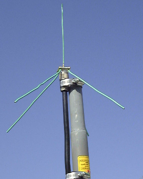
Use Belden 8214 or Times LMR 400 coax and UG21 type N plug with Teflon dielectric at the ground plane end - they are very low loss at UHF and above and water proof. You can use PL259 on the radio end if need be to match the equipment, but they must be made properly to prevent losses and really should not be used above 420 MHz. Hold the N plug to the top of the TV masting with a 2" diameter hose clamp. Align the 1/4 wave vertical element to be as perpendicular to the ground as possible and the 4 radials at 45 degrees. Place the antenna high and in the clear in order to maintain line of sight to the transmitter antenna - 2 or 3 of the 5 foot Radio Shack 15-862 TV masts work well and held in place with a 15-517 mast tripod mount; all are easily transported in a car.
Construction: |
| Frequency MHz | Length in Inches |
| 146 | 19.1 |
| 426.25 | 6.5 as an example in the sketch |
| 915 | 3.0 |
| 1265 | 2.2 |
| 2398 | 1.2 |
| Length of the vertical radiator and 4 radials in inches is 2800 divided by Frequency in MHz. |
|
If you have a SWR meter for the frequency, cut the radiator wire 1/2 inch longer than the table above. Trim the wire 1/8 of an inch at a time and checking for lowest reflected power. It should be adjusted for no more than 10% reflected power. |
|
Go to: The domain of this page is www.hamtv.com - copyright ©2015 W6ORG, all rights reserved. Webmaster contact is ATVinfo at hamtv dot com |
 The Ground Plane vertical omni directional antenna is very easy to build with just some #12 solid copper
electrical wire and a
The Ground Plane vertical omni directional antenna is very easy to build with just some #12 solid copper
electrical wire and a 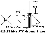 Start by cutting 5 wires a half inch longer than
listed for the desired frequency and strip one
end on each 1/4 inch. Solder the quarter wave
vertical wire to center socket, measure from
flange surface to the top of the wire for the
frequency in use and cut to length. Solder
the 4 radial wires to the respective holes in
the UG-58 jack or bolt on solder lugs and
solder to them. Bend the radials to a 45
degree angle away from the coax and
masting. Then trim to length measuring from
the outer edge of the dielectric to the tip of
the wire.
Start by cutting 5 wires a half inch longer than
listed for the desired frequency and strip one
end on each 1/4 inch. Solder the quarter wave
vertical wire to center socket, measure from
flange surface to the top of the wire for the
frequency in use and cut to length. Solder
the 4 radial wires to the respective holes in
the UG-58 jack or bolt on solder lugs and
solder to them. Bend the radials to a 45
degree angle away from the coax and
masting. Then trim to length measuring from
the outer edge of the dielectric to the tip of
the wire.