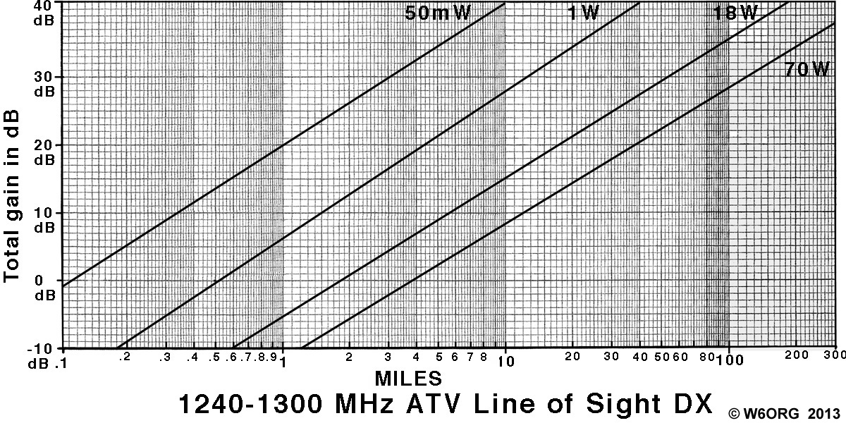
To find the line of sight P5 distance, go across your Total gain dB to your your AM ATV transmitters peak envelope power diagonal line and then go down from that point to find the snow free (40 dB video to noise ratio or P5) line of sight distance.
Total gain in dB = sum of Transmitter antenna gain in dBd (gain over a dipole) plus Receiver antenna dBd gain minus transmitter and receiver coax losses. Figure 1 dB coax loss per 16 feet for Belden 9913, 21 feet for Times LMR-400 and 33 feet for Times LMR-600. If 4 MHz deviation FM ATV add 12 dB; if your downconverter or preamp noise figure is more than 2 dB, subtract each dB above 2. For power levels inbetween the diagonal lines, add or subtract dB's - ie. add 3 dB each time you double the power.
The power level diagonal lines were chosen to reflect the output of our 50-100 mW TX23-.1s Transmitter or added Downeast Microwave linear amplifiers. The older 3 watt RTX23-3 AM ATV transmitter would add 4.7 dB to the total gain when using the 1 Watt line. Check eBay and QRZ.com On Line Swapmeet for our older models.
Example #1: AM ATV repeater transmitter running a RTX23-3 driving a 2318PA Downeast linear amp, 100 ft Belden 9913 coax, Diamond U200 omni being received by a Directive Systems 2424LYRM Loop Yagi, Downeast 23LNAWPQ antenna mounted preamp and TVC-12S downconverter.
Total dB is 9 dB tx antenna - 6 dB coax + 16 dB rx antenna - 0 dB coax = 19 dB.
Going across to the 18 Watt diagonal, the P5 line of sight DX is 16 miles.
Using a Downeast Microwave 2330PATV amp would add almost 3 db giving about 20 miles.
Snow free AM video is received over a 6 mile path between aid stations at the Angeles Crest 100 Mile Trail Race. Power is 1W into a 12dBd gain beam and a TCR-23cm corner reflector on the receive end,.
Example #2: A FM ATV point to point link using a Videolynx Z23B driving a Downeast 2318PA and OAL OAL TCR-23cm corner reflector to transmit, receive with a 2424LYRM Loop Yagi, antenna mounted Downeast 23LNAWPQ preamp and a 23/33FMR-3 receiver.
Adding up 8 dB TX antenna + 16 dB receive antenna - 6 dB 100 ft coax + 12 dB FM advantage = 30 dB on the total gain line. Going down from the 18 Watt line would give up to 54 snow free line of sight DX.
Coax loss is very significant at 23cm. It might be cheaper to invest in larger lower loss coax depending on the length, than a higher power amplifier. For instance, Belden 9913 has about 6 dB/100 ft of loss, LMR-400 about 5dB/100 and Times LMR-600 has 3 dB/100ft. Going from LMR-400 to LMR-600 is less cost than going from the Downeast 2330 amp to the 2360 amp.
Go to:


The domain of this page is www.hamtv.com -
copyright ©2015 W6ORG, all rights reserved.
Webmaster contact is ATVinfo at hamtv dot com
