There are two ways to drive dual Wheel antennas.
First, and probably the easiest, is to order a set of wheels designed and phased for operating as duels and driving them with equal lengths of 50 Ohm coax from a splitter. Everything then is 50 Ohms and the lengths are not critical other than being equal. This is the same for quad antennas driven from a splitter. The Wheels need to be made such that the coax connectors face each other on the mast which requires that one be made for right hand phase and the other for left hand - the direction the wires bend at the circumference after leaving the center pin. It is therefore manditory when ordering Wheels that they will be specified as made for stacking other wise you could end up with up to 3 dB less gain rather than more gain.
 The second method might be preferred for someone that already has one Wheel and wants to stack another. A standard OAL Wheel is made for a left hand bend looking downward from the common feed point side of the coax jack. To use a second standard Wheel, but have the coax connectors face each other on the mast, you need to electrically flip the phase of one180 degrees with a 1/4 wave / 3/4 wave phasing harness made up of 75 Ohm coax. The first 1/4 wave in the 75 Ohm harness from the T matches the 50 Ohm antennas to the 50 Ohm coax to your rig and the additional 1/2 wave on one side flips the phase 180 degrees. To work correctly, much attention must be paid to building the harness accurately to the correct lengths with high quality known velocity factor 75 Ohm coax and connectors, especially as the bands go higher.
A single Wheel antenna has the gain of a dipole omni-directionally. That is to say 0 dBd (scientifically not a good reference) or 2.14 dBi (over an isotropic source). If dBd is used, and it is by many, then in link budgets and other calculations one has to shift back and forth between the two and errors can be made. The dBi gain is calculable from the fact that a "resonate" dipole has a -3dB beam width of 70 degrees (+/-35 degrees of the horizon in the H-plane) by 360 degrees (in the E-plane).
Now if a pair of dipoles are stacked (~5/8 wavelength), the standard thought is that 3 dB is gained. Not really true, one has to consider phasing line loss and other anomalies that will occur. So, the average gain of stacking a pair of Wheels is on the order of 2.14 + 2.8 = 4.94dBi. Another 2.8dB can be acquired by stacking another pair resulting in an array gain for four Wheels of 7.74 dBi. Subtracting the 2.14 dB to get the product to reference a dipole, the gain looks like 5.6 dBd.
One might contend that it's hardly worth the effort to stack four Wheels as compared to just a single one but increasing the EIRP by a factor of 4 might be worth it. The real advantage comes when one examines the beam width reduction in the H-plane from stacking. The -3dB beam width with four Wheels is a little less than 20 degrees or +/-10 degrees of the horizon. Many will argue my gain claims, calculations and research but this is the "free space" truth of the matter.
I have, through the years, heard some fairly ridiculous claims of the gain of the Wheel. Recently one gentleman tells me of his friend, supposedly some antenna guru of notoriety, measuring the gain of a single Wheel to be somewhere between -3 to -6 dBd! I have also heard gains of a single Wheel measuring 5 and 6 dB over a dipole. If one wishes to add in ground gain, height about average terrain and their favorite little fudge factors, fine. The proof of Wheels performance, like most antennas, is in the usage. The math gives us only a rough idea of expected performance but usually falls apart in a real world.
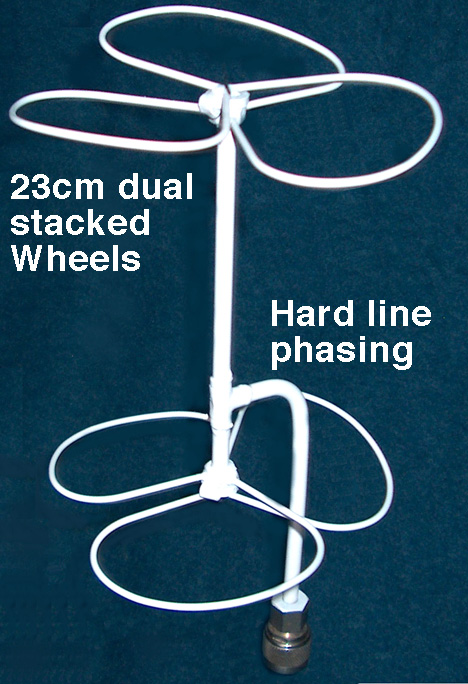
The stacking of Wheels and the preservation of phase in doing so is real subtle and critical. Like most everything there are several ways to stack a pair and four Wheel antennas. The authors and designers of the Wheel came up with a phasing scheme that works quite well but one has to keep their wits about them when creating the Wheels otherwise the array will play like a 30 dB attenuator!. Originally 75 ohm coax having a Vp (velocity factor) of 0.66 was utilized in that one wavelength of coax at this Vp provides a spacing of ~5/8 wavelength between Wheels.
The coax phasing lines are cut into 1/4 and 3/4 wavelength pieces. The top Wheel is fitted with the 3/4 wavelength piece to a coaxial "T". Below the "T" is the 1/4 wavelength piece to a Wheel that has been built inverted or reversed as compared to the top Wheel. A second pair of wheels is constructed the same way but placed upside down to the first. The two Wheels in the middle must then be of the same phase and the bottom one reversed.
How I look at the array when I build one is looking down on the top Wheel if the spokes come out of the hub and go to the right (for instance) then the second Wheel down must have the spokes coming out of the hub and going to the left. The third Wheel down will be phased the same as the second Wheel and the fourth Wheel down will be built opposite phase of the second and third Wheels. Confusing? Yes, to a point, but with a little patience and understanding of what is happening one will persevere.
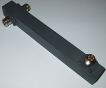
Now, the final phasing lines from the "T"'s that are 3/4 wavelength lines will allow the two center Wheels to be spaced ~5/8 wavelength apart. These two lines now come to another "T" and will allow the array to have a 50 ohm terminal impedance. Trust me, I don't care to go into the math involved that makes this so. I'll leave it as an exercise for the builder if he/she is sufficiently interested.
The 70cm Wheel array phasing lines can be made of 75 ohm cable TV line. The 33 cm Wheel and above arrays coax can be Uniform Tube 75 ohm 1/4" dia. line (expensive), the 50 ohm coax (hardline) for the phasing lines will work but the terminal impedance of each Wheel must be changed slightly from 50 ohms. This is done by manipulating the distance between the spokes.
The easiest method of feeding four or two Wheel antennas is to use equal length, 50 ohm, phasing lines and a power divider - assembly instructions. The two Wheels of the two Wheel array are fitted with type N female connectors at the hubs. One Wheel will be built with right hand phase and the other left hand phase. This is so that when the bottom Wheel is inverted, the connector pointing up, both Wheels will be in phase. Then equal length lines to the two way power divider positioned on a mast between the two Wheels.
In the case of a four Wheel array, the two bottom Wheels must be built the opposite sense of the top ones. The bottom ones will have their connectors pointing up and four equal length, 50 ohm lines are to be connected to the four way power divider that can be attached to the mast between the two center Wheels.
As I have received many questions on the phasing and stacking of Wheel antennas, I hope this will serve to clarify the situation a little better.
Dave Clingerman, W6OAL
Go to: