  |
By Tom O'Hara W6ORG - Email:

Retired owner of P.C. Electronics, The Leader in Amateur Television Equipment for 50 years - history
Last update May 12, 2024
This app note describes the characteristics of Frequency Modulated Amateur Television.
|
By Tom O'Hara W6ORG - Email: Retired owner of P.C. Electronics, The Leader in Amateur Television Equipment for 50 years - history Last update May 12, 2024 This app note describes the characteristics of Frequency Modulated Amateur Television. |
|
FM ATV occupied bandwidth and spectrum power density is much greater than AM ATV. Therefore FM ATV is not used below 902 MHz and even though it would be legal on the 70 cm band, it would not allow other mode users and interfere with weak signal and satellite reception in the middle of the band. 1252.0 MHz is the most used FM ATV frequency in the USA to keep away from FM voice repeaters. On the 33cm band, 915.0 is used to stay centered in the band and sidebands inside the band edges. 2441.5 MHz is near the upper band edge and allows for other channels below for links on 13cm. ATV with Gunnplexers can be found on 10.40 gHz. 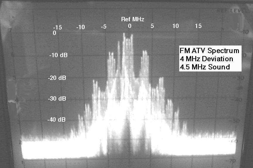
Most FM ATV in the USA was on the 23 cm band primarily due to the availability of British FM ATV gear and the low cost of C band satellite TV receivers in the late 1980's. Today, it is difficult to find C Band satellite TV receivers and they are being replaced by imports designed for the video security market or license free FCC Part 15 A/V equipment modified for the ham bands. P.C. Electronics sold their last Bensat satellite receiver in 2002 and 23/33FMR receiver in 2007 which we modified for the 900 &1200 MHz amateur bands. The standards in the USA went along with the satellite receivers as far as the sound subcarrier at 5.8 MHz and 50 kHz deviation. Also the CCIR 405-1 pre-emphasis / de-emphasis curves were used. Video deviation, however, adopted the 4 MHz standard used by the TV broadcast industry for studio to transmitter site links and news gathering trucks even though the satellite receivers are made for 11 MHz deviation. With the lower deviation, in order to get the 1V peak to peak video out of the satellite receiver, one had to get inside the receiver and crank up the video gain to compensate or use an external video amp with a gain of 3 such as the GVM-1 board. The IF bandwidth is also wide on these satellite receivers at 27 to 34 MHz which reduced the sensitivity of the system due to excessive noise power. Also, 20 to 30 dB of gain had to be added for the early satellite receivers which were designed for -60 dBm input from a downconverter or LNA. Current security receivers typically have 17 or 21 MHz IF bandwidth which is optimum for the 4 MHz video deviation and don't require a preamp unless you have a lot of coax loss. These receivers use 5.5 MHz on the 900 and 1200 MHz bands but can be used with 5.8 sound with a slight tweek of a variable inductor. However, 5.5 MHz is becoming the standard. 6.0 and 6.5 MHz sound is used on the 2400 MHz band and 6.2 and 6.8 MHz on 3.3 and 10 gHz bands. Security transmitters and receivers do not have pre-emphasis / de-emphasis of the video which is strange because it can greatly increase DX at very little cost. Resolution is a function of response bandwidth and with NTSC video, it is about 85 lines per MHz regardless of transmission method. Resolution (the number of vertical lines you can distictly see without bluring across the screen) is often confused with the number of scan lines and rates. Horizontal scan rates do limit the number of horizontal lines you can see from top to bottom and in a NTSC system with 525 interlaced scan lines you might be able to see 240. Possible resolution is limited by the color and sound subcarriers also in either transmission system. If there are no color or sound subcarriers and you are only interested in high resolution black and white video, then it can most easily be obtained in an FM system that outputs to a high resolution monocrome video monitor. However, if you use a TV set or color monitor then your black and white resolution limit will be about 255 vertical lines (3 MHz times 85) due to the video low pass filtering at 3 MHz to reduce intermod with the 3.58 MHz color subcarrier. Color vertical resolution is limited to about 100 lines from the color IF bandwidth of a little over 1 MHz and available color pixels on the screen.
| ||||
|
Pre-emphasis and De-emphasis Pre-emphasis in the FM ATV transmitter along with corresponding de-emphasis in the receiver can more than double the distance or add a P unit for the same distance (6 dB) by lowering the noise floor in the receiver.

The pre-emphasis network can be added in the composite video line to any FM ATV transmitter if it does not have one and is used in your area. You will end up with greatly distorted video if some ATVers in the area use it and others don't. The pre-emphasis network attenuates the low frequencies about 10 dB below 750 kHz so the video gain has to be increased to compensate - the GVM-1 Gunnplexer Video Modulator Board can also be used for pre-emphais and the added gain. Likewise, the video gain in the receiver has to be increased to compensate for the attenuation of the high video frequencies and color subcarrier. 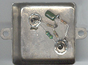
The networks shown use standard value parts and are close enough even with 5% tolerance as long as you make sure the outputs are connected to a good 75 Ohm resistive termination - check with an Ohm meter. Check the Mouser or Digi-Key parts catalogue. You can either disconnect the wire to the video connector in the transmitter or receiver and insert in series, or mount the parts in an small aluminum box with jacks if you want to do it externally. You can order a PEK Pre-Emphasis or DEK De-Emphasis (pictured) kit including the metal can and RCA jacks from us for $15. Mouser Part Numbers Used:
If your transmitter or receiver does not have enough video gain to compensate for the loss through the pre-emphasis or de-emphasis network, we have a board that has an adjustable gain of up to 5 with pre-emphasis built in that can be used. The GVM-1 board can also be used for de-emphasis with analog TV satellite receivers by changing 5 parts. References: Occupied Bandwidth: Per FCC Rule 97.3(a)(8) it is the width of a frequency band outside of which the mean power of the transmitted signal is at least 26 dB below the mean power of the transmitted signal within the band. Carson's Rule for FM occupied bandwidth is a good rule of thumb to estimate what the 26 dB down point will be given deviation and highest modulating frequency. The formula is 2 times deviation plus 2 times the highest modulating frequency. Therefore with 4 MHZ deviation and 4.5 MHz sound, the occupied bandwidth would be 17 MHz - this is pretty close as can be seen in the spectrum analyzer photo above. However, the formula is based on the highest modulating frequency being a sine wave at full deviation. |
Go to: The domain of this page is www.hamtv.com - copyright ©2024 W6ORG, all rights reserved. Webmaster contact is ATVinfo at hamtv dot com |
 DX line of sight can be over 22 miles running a
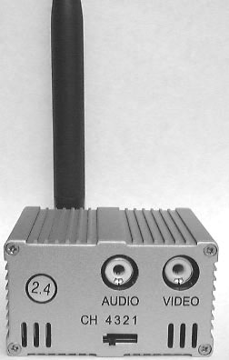
 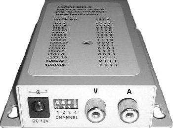 FM ATV can be more expensive and not as easy to get on vs. AM ATV. TV sets are AM and require no modification to receive ATV on 70cm if they have a cable ready tuner - Except for the antenna, receiving 70cm AM ATV is practically free. For FM, you need a complete FM ATV receiver which outputs composite video and line audio like the 13FMR-1 shown at right for the 2.4 gHz MHz band. Some have AM channel 3 modulators built in so you can use a TV set rather than direct connect to a video monitor with A/V inputs. An external channel 3 modulator can be added and the A/V cables plugged in if prefered. Transmitters are about the same cost and easy to get on the air. Amps can be added without need to be some what linear, however they typically require more attention to heat sinking and the addition of a coolin fan since they run at full CW ratings for long keydown periods.