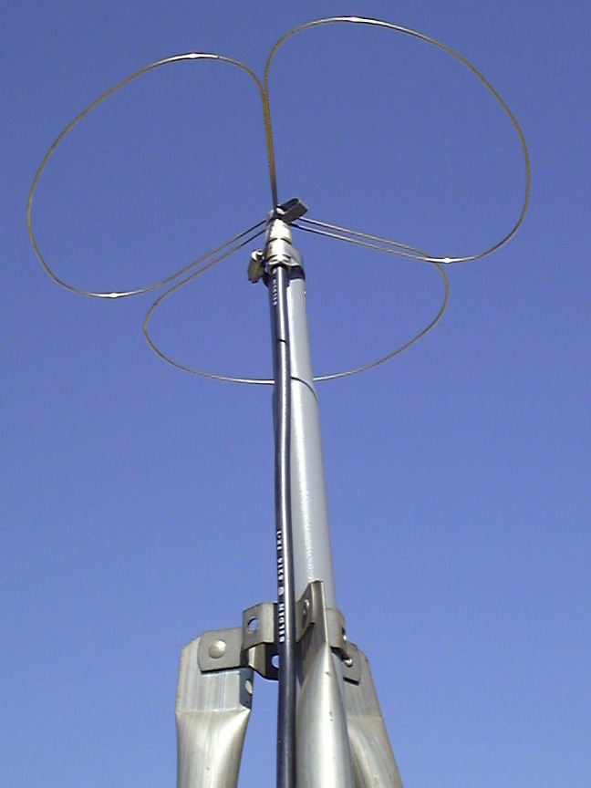
The Wheel antenna has been around since the early 1950's, first used in the Amateur Radio Two Meter band as a horizontally polarized omni radiator. The Wheel resembles a skeleton three leaf clover. The elements themselves are one wavelength of material each at the band of interest. The outermost side of the element is a half wave dipole; thus three half wave dipoles around the perimeter of a circle. These dipoles are then stood off from the hub by quarter wavelength sections at each end of the dipole; therefore, being fed at the ends rather than the center of the conventional dipole. Modeling this antenna can be done so by treating each "leaf" of the three leaf clover as a broad banded quarter wavelength monopole. Each monopole will exhibit a 36 ohm terminal impedance and therefore the paralleling of the three results in a combined impedance of 12 ohms. Observed on the Smith Chart of a network analyzer will present a fairly inductive device at the frequency of interest. A capacitive stub (a strap of metal less than a quarter wavelength in length) is employed at the hub to balance the inductance and bring the terminal impedance to 50 ohms. VSWR is less than 2:1 over a 5% bandwidth - a Wheel centered at 435 MHz for instance would cover the transmit range of 425 to 445 MHz which is good for the most used ATV frequencies from 426.25 to 439.25 MHz. 421.25 could still be used for receiving without retuning.
Wheels make a simple low cost horizontal broadbandwidth omni antenna for use at at repeater site. The Wheels can be vertically stacked at 5/8 wavelength spacing for more gain (2.8 dB additional for 2 and 5.6 dB for a quad) and fed with equal lengths of coax from one of the OAL splitters. However, all Wheels must be ordered at the same time and configured for stacking. You cannot simply use one wheel and then just order additional ones to stack for more gain as the single wheels are designed for the right hand circular above and below, but the stacked version must be built for left hand circular to phase correctly.
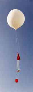
Around 1990 the first launch of a balloon borne payload in the Denver, Colorado Area took place sporting a Little Wheel as the radiator for the on-board ATV transmitter. It was found to work quite well and had some interesting attributes that were previously undisclosed. Those being that the Wheel antenna although being a horizontal radiator on the horizon displayed properties of cross polarization above and below the array - similar to two in phase horizontal dipoles. This worked to the advantage of the ground station by employing a circularly polarized antenna (Helix) - also a fixed horizontal antenna directly below at the launch site would not see the up to -30 dB nulls as the balloon rotated. The horizontally polarized tracking antennas (Yagis) were receiving a signal of constantly changing polarity as the payload rose to an altitude at which it would start to drift away from the launch site and the horizontally polarized tracking antennas would become more effective due to the horizontal polarization emitted from the sides of the Wheel.
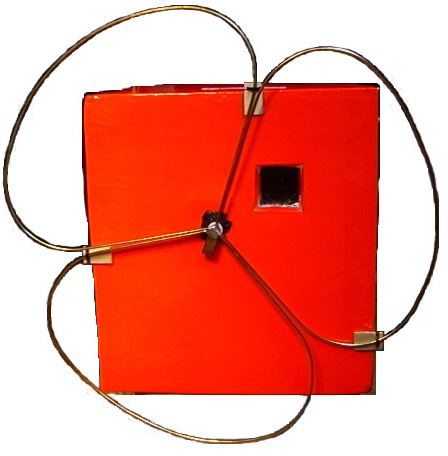
Photo by N8QPJ at right is a Balloon payload with a OAL Big Wheel mounted at the bottom of the package. Square hole is for the camera.
To date, Wheels have been created for every conceivable airborne, sea borne, space borne and terrestrial vehicle known to man (save the Frisbee). The pattern of the Wheel is within +/-0.5dB of being a perfect circle in the E-plane. In the H-plane the pattern is +/-35 degrees of the horizontal axis of the antenna. These figures equate to ~ 4.28 dBic gain or 6.38 dBdc. The dBic gain above and below the array is somewhat indeterminable due to the fact that the circular polarization exhibited is quasi-circular or cross polarized; however, it responds to a Helix in a manner consistent with the gain of a pair of like sense Helices in a system looking at one another.
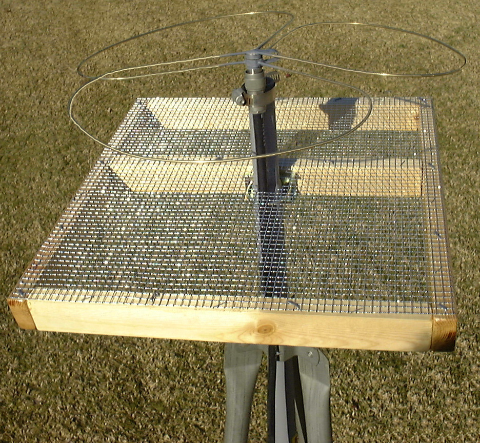 Gain downward from an airborne payload can be improved with the use of a reflector placed ~0.2 wavelength above the Wheel. The improvement is on the order of 2.8 dB (not 3.0 dB, as that is only a theoretical figure). To create such a reflector, the top side of a 5 inch thick payload could be used or or under surface of a payload might be considered for such duty with the wheel fastened 5.5 inches below on a short length of PVC pipe. Basically, any circular metallic mesh that is 5% larger in diameter than the periphery of the Wheel will suffice. This might be a consideration for a fixed ground station or launch site antenna - like shown at right - vs. the Helix or circular polarized yagi like the 7CP-70cm 7 Element Circular Beam for balloon borne payloads and rockets.


