 For optimum DX and receive sensitivity, the first preamp stage in a receiving system should be placed directly at the antenna to avoid the coax loss. The first stage should be the lowest noise device in the system and can either be part of the downconverter or a stand alone preamp. There are some pluses and minuses to antenna mounting downconverters vs. an antenna mounted preamp or low loss coax. This app note also describes mounting our TVC-xS series downconverters in a Hammond 1590B die cast aluminum box.
The Pluses: It is more important to minimize coax loss with FM ATV systems than AM ATV since the picture to noise ratio changes more rapidly. With AM the picture to noise ratio is dB for dB with 6 dB being one P unit or half the distance for the same picture to noise level. An acceptable rule of thumb has been 3 dB or less coax loss or greater than 100 ft of Belden 9913 or LMR-400 on the 70cm band for instance, before considering expending time and money on an improvement. With FM it depends on the modulation index and how good the limiter is - given the 4 MHz deviation standard we use on the 902 through 2400 MHz bands and poor limiting found in today's IC PLL or quadrature detectors it is about 2-3 dB for each dB of coax loss. The higher bands have much more coax loss so having the first stage as close to the antenna as possible is much more significant. Many may try ATV by first getting a down converter and antenna to receive the local repeater output. If everything practical has been done with antenna gain and positioning, and the picture still has some snow in it, then eliminating the feed line loss is the next step. If the repeater is crossband, and you don't have to transmit on the repeater output band, then just adding an antenna mounted preamp might be the best way to go. If you don't mind a little solder slinging, then you can repackage the downconverter board in a weather proof box for antenna mounting and build a bias-T at both ends to power it up the RG6 coax. The bias T consists of a .001 mF coupling cap to block the DC from the TV input and a 4.7 uH inductor to block the RF and connect power to the downconverter. The coax to the shack can be hundreds of feet of RG6 which has 1.5 dB loss at ch3 and 2.5 dB at ch 8 per 100 ft. The downconverter has plenty of spare gain to throw away in the output coax. To transmit on the same band, you must add the complexity of T/R switching.
The Minuses: Primarily it is cost, complexity and reliability. As mentioned, if you want to transmit on the same band, you need to build in a RF T/R relay system. RF coax relays for UHF and above are not cheap and you need to sequence the DC and RF so that you don't transmit into an open coax for too long and that there is enough isolation between the two relay ports such that the transmitter does not blow the preamp. Max RF at the preamp should not exceed a few milliwatt's.
Effective weather proofing is important so that moisture does not get in and ruin the circuit. The box generally needs to be constructed to have seams and connectors only on the side pointing to the ground. Temperature is also significant especially in areas with weather extremes. Most ham gear is not designed or even tested to see how it does below freezing - a proportional resistive heater is some times used in this case. Our TVC-xS downconverters are crystal controlled so temperature drift is not a problem. For info on antenna mounting our older tuneable ATV downconverter download this app note. With tunable downconverters the LO frequency will probably drift and require slight frequency dial adjustment every 10 degrees of outside temperature change or so - this may or may not be a source of annoyance. The TVC-2G only drifted 340 kHz from 75 down to 5 degrees F which is in the range of most TV AFC's if tuned in the center. Higher bands will shift more.
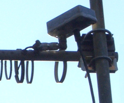 Repackaging: The downconverter shown below is built into an Hammond 1590B die cast aluminum box. All holes are in the cover so no moisture can get in when mounted parallel to and facing the ground as shown in the photo on the right - 23cm downconverter mounted on a Loop Yagi with a right angle N adaptor and a double male N adaptor. The ridge on the cover needs to make good shielding contact with the bottom so do not use a silicon sealer between them. The cover ridge should be high enough to let gravity keep the moisture out. A silicon sealer is used on the outside of the seam and around all connectors once the system tests out.
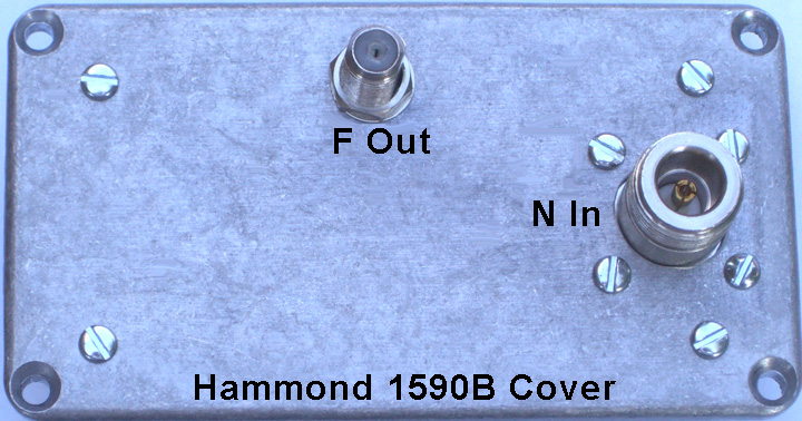
 The board is first placed and centered on the inside of the top cover. This way the 4 1/8" dia mounting screw holes can be marked and then drilled accurately. Then drill a 1/8" pilot hole directly between the two board mounting holes on the output side for the F-61 jack. On the input end, drill the pilot holecentered and 3/4" in from the cover end. Finish drilling the F jack to 3/8" and punch or drill a 5/8" hole for the UG-58 N antenna jack. Place the UG-58 jack in the hole and mark and then drill the 1/8" diameter holes for the four 4-40x5/16", lock washer and nut. Debur all holes and check for fit.
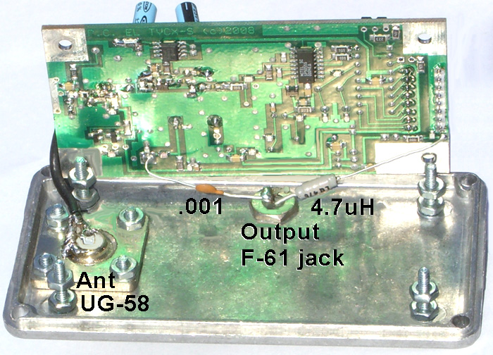
Mount the F-61 jack and wrap one end of a .001 mF disc cap and a 4.7 uH inductor around the center pin terminal as close to the insulation as possible and solder. The cap lead must be long enough to reach the TV output of the board and the inductor to the + voltage input. Cut off the excess terminal as close as possible to the wires. This is necessary to clear the bottom of the board. Mount the UG58 jack and pre-tin an area on the flange next to the insulation for soldering the shield of the coax. Cut a piece of RG174 50 Ohm coax to about 2". Strip the outer insulation back 1/4 inch on each end and fold back the braid. Strip the center conductor 1/8". Carefully pre-tin the center and braid, then check for shorts. Place one end on the pretined section of the N jack and quickly solder. Let cool then solder the center conductor to the center pin as close to the insulation as possible and clip off the excess. Again, check for shorts.
Put in the four 4-40x5/8" board mounting screws and secure with a lock washer and nut - you can use a 3/8" spacer instead of the 2 nut method shown. Then put a nut on each one and thread down about 1/4" from the end. Place the board on the screws to check alignment, then tighten the screw and nut that is against the cover. Place the board as shown in the above photo and solder the .001 mF cap to the output solder pad and the 4.7 uH to the + power input solder pad.
 Rotate and place the board on the screws and secure with nuts on each screw down to where the screw top is just flush with the nut, then tighten the respective nut on the bottom of the board with a 1/4" end wrench. Check to make sure none of the connectors are touching the bottom of the board. Check that there are no shorts on the F61 jack center to ground and the wires are equally spaced between the board and cover. Bend the RG-174 over and while holding the insulation lightly against the top of the board, solder the braid to the board ground plane. Then solder the center conductor after the shield has completely cooled. You wont be able to check for shorts now because the downconverter input is at DC ground through an inductor.
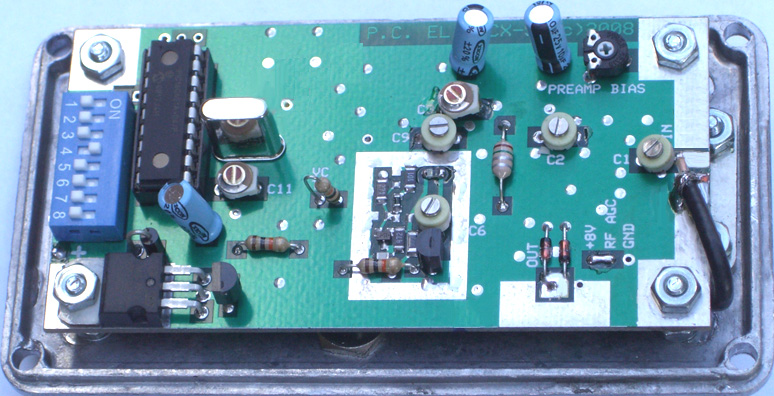
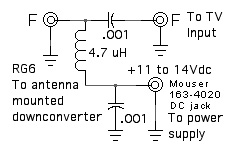 Set the desired input and output frequencies with wire jumpers or a digiswitch - photo above is a TVC-12S set to 1277.25 in and channel 8 out. Make a DC power bias-T with a .001 mF coupling cap and 4.7 uH inductor in the same manner as was done at the downconverter output. This can be made in a 2x2x.88" metal can similar to the app note for a Antenna Mounted Preamp bias-T only using two F-61 jacks, two .001 mF caps, 4.7 uH inductor, and a coaxial DC power jack.