  |
All about Amateur Television - ATV
Ham Radio with Vision
Hosted by Tom O'Hara W6ORG
Email:

Retired owner of P.C. Electronics, The Leader in Amateur Television Equipment for 50 years - history
Last updated March 4, 2019
ATV in Rockets and Balloons
|
All about Amateur Television - ATV Ham Radio with Vision Hosted by Tom O'Hara W6ORG Email: Retired owner of P.C. Electronics, The Leader in Amateur Television Equipment for 50 years - history Last updated March 4, 2019 ATV in Rockets and Balloons |
|
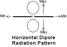
Rockets, balloons, kites or other vehicles that are predominantly flown overhead and using ATV present a unique antenna radiation pattern problem. For strongest picture and best distance (DX), antenna radiation patterns should have their major power lobes pointed at each other and the same polarity. A vertical dipole omni directional antenna in the vehicle is fine for best DX on the horizon where the receive end will be at no more than a 15 degree angle perpendicular from the antenna. For example if the vehicle is expected to go 1 mile vertically, those at 4 miles or more away will be with in the maximum radiation lobe of the antenna and get the best video. Those less than the 4 miles would be within the null or minimum radiation patterns with weaker and erratic signals. If the rocket antenna is a 1/4 wave vertical spike on the nose and the body of the rocket the ground plane, the main lobe can have an uptilt of 15 to 20 degrees above the horizon where some of the signal will be wasted. So we suggest using a horizontal dipole on the vehicle and circular polarized antenna on the ground if received directly below. Circular polarity is necessary to minimize the signal strength variation as the vehicle spins. One watt on 426.25 MHz with our TXA5-RC series board or Videolynx VM-70X transmitter, dipole antennas at both ends will give good snow free line of sight color pictures to over 2 miles. With beams on the ground, each 6 dB of antenna gain or power doubles the distance for the same signal strength at the receiver. If snow free (200 uV) is 2 miles dipole to dipole, color will start to drop out around 8 miles, but still be seen out to 20 miles or more. See DX example #3. Also note that given the same power and antenna gains, the lower the frequency, the farther the distance. For instance the 902-928 MHz band goes half the distance as the 420 MHz ham band, 1.2 GHz 1/3 & 2.4 GHz 1/6. Payload weight, most will be in the battery you select for length of transmit time - VM-70X transmitter module is 2.5 oz and the CG35A mini color camera 2 oz. For more general information on ATV and all facets of ham radio, I suggest reading the ATV section in the 2011 ARRL Radio Amateurs Handbook beginning on page 32.9 (check your library or order from ARRL at 1-888-277-5289). |
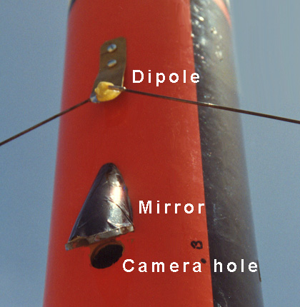
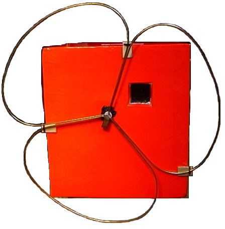
Inverted V horizontal dipole |
|
ROCKET ANTENNA. It is difficult to place an antenna on a rocket that will have any radiation efficiency and a power pattern that favors the earth directly below. For non-metallic diameters more than 4.5 inches a copper tape dipole around the inside diameter, or epoxyed embeded on the outside can be used. Try to keep anything metalic as far away as possible from the antenna to minimize the effects on the antenna radiation pattern. For smaller diameters or metallic body, an inverted V dipole antenna mounted on the side can be made with two 6.5 inch pieces of piano wire which are crimped into #6 solder less ring tongues - Radio Shack RS64-3030. Two 6-32 screw holes are drilled in the rocket body 3/8 inch apart. If the rocket body is conductive, the screws must have insulation around them. Mount the two dipole elements and angle about 30 degrees from horizontal to help with the aerodynamics. Use #6 solder lugs inside for the RG174 coax connections. Carefully solder the sleeve balun and check for shorts. Trim for minimum VSWR. Epoxy in place. If the rocket body is thin cardboard, you can use a 1x3" strip of brass as shown in the photo, and mount the wires to a BNC chassis jack. Cameras are usually mounted inside with the lens facing out on the horizon through a small hole - try to keep the spin to a minimum or you might get dizzy watching. You can also use a prism or split mirrors outside to show above and below split screen or a single mirror just for below. Your Call ID with GPS data giving altitude, speed, bearing and direction to the launch point can also be overlayed using an OSD-GPS+w/c board and GPS receiver like the Garmin 15. You may need a MiniCircuit Lab VLF-490 low pass filter in the antenna line to keep harmonics out of the GPS receiver. |
 |
|
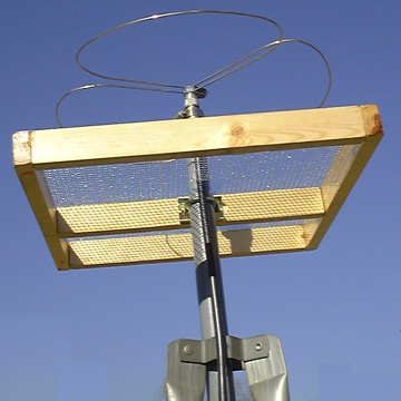
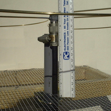
LAUNCH SITE RECEPTION. Horizontal polarization radiating downward is the most practical if launch site reception is the most important. As a rocket or balloon spins, single polarity horizontal antennas will go into a null as the two antennas rotate into right angles to each other and back out to maximum power when parallel. To prevent this spin amplitude modulation with either a rocket or a balloon, one end needs to use circular or cross horizontal polarization. On a rocket, a single dipole is the most practical and will give a good radiation pattern out to about 45 degrees - receive coverage horizontally out about the same distance as the rocket altitude to a circular or crossed polarized antenna pointed at the rocket. Balloons can hang a horizontal dipole and be received in the same way as the rocket, but conversely, it could also use a circular or horizontal cross polarized antenna like a Little Wheel on coax dangling below the transmitter payload package and be received by a horizontal antenna on the ground. The Wheel antenna has the advantage of radiating or receiving on the horizon quite well and cross horizontal polarized above and below it. The Little Wheel with reflector is a great low cost antenna to use at a rocket or balloon launch site when the vehicle antenna is also horizontally polarized. The circular polarized turnstyle is also popular for the home brewer and is shown later in this application note. A circular polarized beam like the OAL 7CP- 70cm shown right, will have some gain which can double the distance for the same picture for each 6 dB of gain or improve a weak picture by 1 P unit. TV's manufactured after 2008 typically contain sensitve analog cable TV tuners in them and will probably work quite well as is to receive the signal from the rocket or balloon. Older TV's with or without a cable tuner (ch 58-60) can be used with our TVC-4S downconverter connected to a TV on channel 3 or to the Rch3 receiver if you want to drive a monitor. A cable TV tuner to USB box connected to a lap top can also be used in the field. TRANSMITTING. There is a trade off of transmitter power vs. weight vs. flight time. The battery therefore is the heaviest and the limiting factor in your payload. For shorter distances, you can get good video receiving with a OAL 5L-70cm or OAL 7CP- 70cm beam for over a mile using the 50 mW Videolynx 434 transmitter, mini color camera, home made dipole or ground plane, and 9V alkaline battery for 2 hours flight time and weighing 8oz. With two 9V alkaline batteries, you can get over 8 hours flight time. Higher altitudes take a little more systems thought because temperature and heat dissipation as well as longer flight times come into play. You will need to run the 1W TXA5-RCs transmitter board or adjustable up to 5 W Videolynx VM-70X transmitter module to get not only up to 100,000 feet altitude, but in all probability the jet stream can take the vehicle out tens of miles horizontally. The maximum VM-70X mounting plate temperature is 149 degrees F. You can mount the VM-70X on a 3 x 8 inch piece of sheet copper or aluminum to conduct the heat to the outside surface of the package through a slit cut in the vehicle or package wall. Use heat sink grease between the mounting plate and foil. The sheet is then folded upward, formed and glued to the outside surface. The VM-70X module is then mounted to the bottom side of the sheet metal heat conductor and the antenna jack pointing down. So before flying your payload, monitor the the mounting surface with a thermometer and add to heat sink surface area or decrease RF power as required to keep the temperature below 149F after 30 minutes. A 50K thermistor can be put in parallel with the RF power pot on the board to run higher power at the colder altitudes but reduce power when hot - See the test notes. BATTERY. Select an 11 to 14V battery that has the least weight and will give you at least twice the transmitter and camera current draw times the longest flight time anticipated - check out those available for electric R/C aircraft at hobby shops. For example, if your system draws 1/2 Amp, select a battery that is rated at 1 Amp/hour times the flight time. Nickel Metal Hydride batteries weigh about 7oz per Amp hour, come in 12V sizes, and Lithium Polymer batteries are about 2.5 oz but take more care in charging and come in 11.1 or 14.8V packs - however, you could use two 1A diodes in series to drop the 14.8 voltage to safe levels. Lithium Iron Phosphate (LiFePO4) batteries are 3.3Vdc and hold to about 3.2Vdc during discharge. Two 6.6V packs can be put in series for 12.8Vdc under load, are light weight and come in various Ah sizes - Hobbico LiFe Source LM0842 6.6V 1900mAh is 3.5oz. The Tekkeon MyPowerAll MP3450 is a Lithium Ion pack that can be set for 5 to 19V, weighs 16oz and rated at 4.8 Ah at 12Vdc. DISTANCE. See the ATV DX graph which gives the expected line of sight snow free video distance given transmitter power vs. antenna gains. For best consistent signal away from the launch site an omni directional antenna needs to be on the vehicle so it radiates equally toward the horizon in all directions as it spins. Physical restrictions may prevent using an omni directional horizontal antenna on rockets with metalic bodies or are less than 4" diameter. If you are transmitting to another ham's home station, then the polarity will probably be determined by what they have up, and the standard in the area. If that is not a factor, a vertical omni is usually the easiest to mount. On Baloons and kites you can hang an upside down quarter wave vertical ground plane made from some wire and a coax connector (see our ground plane and R/C ATV app note. An upside down ground plane will have maximum radiation about 15 degrees below the horizon and a null directly below at the launch site - the null may not be a significant factor with the vehicle close or if it travels off at an angle. With rockets, a vertical omni can be placed inside if the rocket body is not metalic and away from metalic objects. If you want both good launch site signal at a small sacrifice in power on the horizon, then a horizontal omni on the vehicle would be best. On balloons, the OAL Little Wheel would radiate horizontal polarization on the horizon and circular below. Beams of the same polarity of the vehicle can easily track the signal by varying the beam heading for best picture, however keep in mind the tradeoff of the higher the antenna gain, the narrower the beam width and tracking sensitivity. For instance, the DSFO-ATV25 element beam has about 16 dB gain over a dipole and 23 degrees of half power beam width that would have to be moved to follow the vehicle in both azmuth and elevation. In the field, the OAL 5L-70cm 8 dBd antenna has a forgiving 70 degree beamwidth and is quite easy to handle portable with its' 31 inch boom. REFLECTOR FOR THE WHEEL ANTENNA. A reflector can give you 3 dB more gain compared to a single wheel antenna and concentrate the RF where you want it to go. The reflector is placed .2 wavelength below the antenna and it's diameter must be at least 5% larger than the diameter of the wheel. Construction is basically the same as the Turnstyle but I made it from 1.5 x 3/4 wood stock and mounted to a metal mast. It could also be made with sheet metal cut circular and no frame. Two pieces are 15.5 inches long and 3 pieces are 14 inches. The pieces are drilled and screwed together with two holes spaced 3/4 inches apart at each location on the 15.5 inch pieces using 1.5 inch #8 flat head wood screws. The center 14 inch piece has two 5/16 diameter holes drilled in the center for a Radio Shack 15-826 mast clamp and inside spaced 5 inches from one side. Two coats of spar varnish are put on the wood before fastening the 1/4 inch mesh 15 inch square hardware cloth with double pointed tacks. Cut a key hole in the hardware cloth sighting down through the mast clamp and allowing room at the bottom of the keyhole for the coax. The whole assembly is easily broken down for portability. Pass the coax through the keyhole, then drop the reflector over and down the mast. Mount the Wheel to the mast with a hose clamp. Move and measure the 5.5 inch spacing from the lower element of the Wheel to the reflector and tighten the mast clamp. For launch site use the antenna is best placed just above head height with plenty of clearance towared the vehicle. 426.25 MHz TURNSTILE CIRCULAR POLARIZED ANTENNA. The 146 MHz Turnstile is commonly used by home brewers for satellite work and originally from the ARRL Antenna Book 14th edition and Sept. 74 QST. We have scaled and noted the dimensions for 426.25 MHz. The quarter wave phasing and matching sections are for RG-59A/U coax, but if you use any other coax, find out its velocity factor and use the formula: L=Vf times 234/FcMHz. For those who want to buy a ready made antenna we suggest the M2 EB432 Eggbeater with reflector available from ham radio dealers. CONSTRUCTION The mast used to support the two dipoles is made of wood, being 2 inches square and 8 feet long. The dipoles may be made of no. 12 copper wire, brass rod or tubing up to 1/4 inch diameter. Mount the two 6.5 inch dipole pieces on one side of the mast and centered and 1/8 inch feed point spacing with 3/ 4 inch long #6 wood screws. The other dipole is 1/4 inches above the other on another side. The RG-59 coax pigtails should not be longer than 1/4inch long. Carefully solder on the coax and phasing line then check for shorts. Run the coax and phasing line down the mast. The spacing from the screen to the dipole is 9.5 inches for satellites and 5.5 inches for rockets and balloons. Two holes spaced 1 inch apart can be drilled for two 1/4-20 x 3.5 inch machine screws to hold the mast to the frame. Off set the frame cross piece so that the dipoles are roughly centered and snip a 2 inch square clearance hole for the mast and enough on one side to clear the coax and connector. Lash the coax to the mast with enough plastic cable ties that the coax cannot be pulled on and break the dipole solder connections. Drill the matching holes in the frame. For more portable use, the machine screws will allow removing the mast for transport. The mast can also be made in pieces. The reflecting screen is hardware cloth with a minimum of 1/2 inch mesh. It can be cut from a standard 18 or 24 inch roll to 15 inches square. The frame and mast is made from 1x2 inch wood. Cut two pieces 16 inches long and three 14 inch long. The screen is stapled or fastened with double pointed tacks to the 1 inch side. Before putting on the screen, a few coats of spar varnish is suggested on the wood. Cover the coax and dipole solder connections with silicon rubber. |
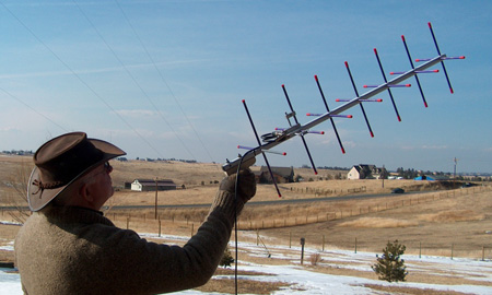 Circular polarized OAL 7CP-70cm antenna can be hand held and pointed at the vehicle for maximim signal as it travels.
|
|
Go to: |
|
The domain of this page is www.hamtv.com - copyright ©2019 W6ORG, all rights reserved. Webmaster contact is ATVinfo at hamtv dot com |

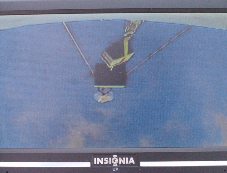 Received video on a portable TV from a decending balloon looking down on an instrument package and to the clouds and ocean below. Slant distance is about 20 miles line of sight. Transmitter is a P. C. Electronics TXA5-RCb to a Little Wheel antenna, and receiving on an Insignia 7" portable TV connected to a 3 element hand held beam antenna.